Quick reference for the PSoC6™
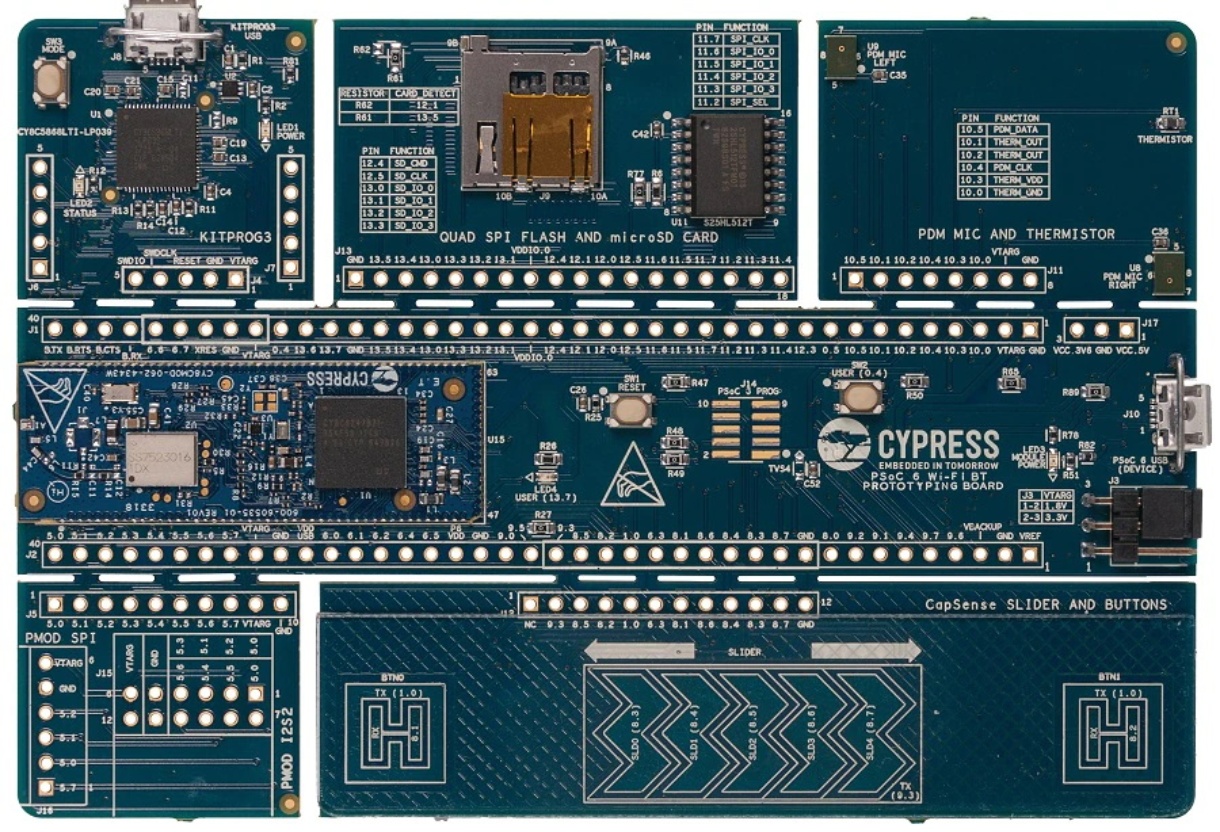
The CY8CPROTO-062-4343W PSoC6™ Board.
Below is a quick reference for PSoC6™ boards. If it is your first time working with this port it may be useful to get an overview of the microcontroller:
And if you are already familiar with MicroPython enablement for PSoC6 and want to try it’s integrations in other application domains, check below:
Note
The PSoC6™ port is now a mature port and is expected any MicroPython built-in library to be supported, but not all libraries, modules and features may have been implemented yet. For modules relying on platform and hardware dependencies, only those listed and documented in this quick reference are supported.
Please consider opening an issue or discussion on GitHub for clarification on available features or to request missing features.
General board control
The MicroPython REPL is accessed via the USB serial port. Paste mode (Ctrl+E) is useful for pasting large sections of Python code into the REPL.
This port implements most of the methods described in the machine module. Tab completion is useful to
find out what methods an instantiated object has.
The machine module:
import machine

machine.freq()                                  # get the current frequency of the Core M4
machine.freq(machine.CM4, freq)                 # set the frequency of the Core M4 sourced by PLL to freq. Value of freq can be upto 150 MHz
machine.freq(machine.CM4_FLL, freq)             # set the frequency of the Core M4 sourced by FLL to freq. Value of freq can be upto 48 MHz
machine.freq(machine.AUDIO_I2S_98_MHZ)          # set the frequency of the I2S clock to 98 MHz
machine.freq(machine.AUDIO_I2S_90_MHZ)          # set the frequency of the I2S clock to 90 MHz
machine.freq(machine.AUDIO_PDM_24_576_000_HZ)   # set the frequency of the I2S clock to 24576000 HZ
machine.freq(machine.AUDIO_PDM_22_579_200_HZ)   # set the frequency of the I2S clock to 22579200 HZ
Delay and timing
Use the time module:
import time

time.sleep(1)           # sleep for 1 second
time.sleep_ms(500)      # sleep for 500 milliseconds
time.sleep_us(10)       # sleep for 10 microseconds
start = time.ticks_ms() # get millisecond counter
delta = time.ticks_diff(time.ticks_ms(), start) # compute time difference
start = time.ticks_us() # get microsecond counter
delta = time.ticks_diff(time.ticks_us(), start) # compute time difference
Pins and GPIO
Most of the methods (functions) and constants given in the machine.Pin class have been implemented in this port. Any functions in addition to those or function calls with an ambiguous list of parameters have been documented here with suitable examples.
The constructor
The constructor can be called in different flavours and configurations based on the number of arguments (parameters) passed.
An instance of the machine.Pin class can be created by invoking the constructor with all the necessary parameters to fully configure the Pin.
from machine import Pin

p0 = Pin('P13_7', Pin.OUT, value=0)   # create output pin on pin P13_7,
                                      # with initial value 0 (low)
Additionally, with any combination of parameters (except the Pin number or id which should be passed mandatorily), a machine.Pin object with various configuration levels can be instantiated. In these cases, the Pin.init() function has to be called proactively to set the other necessary configurations, as needed.
Moreover, a pre-configured pin object can be repurposed by calling the Pin.init() function.
from machine import Pin

p0 = Pin('P13_7')       # create pin object for pin P13_7.
p0.init(Pin.OUT)        # set pin as output.
p0.low()                # set value low.
Similar to CPython, the parameters can be passed in any order if keywords are used. On the other hand, in case of a non-keyword assignment if a parameter is not to be set, a None is to be passed in its place.
from machine import Pin

p0 = Pin('P13_7', value=0, mode=Pin.OUT)     # create output pin on pin P13_7,
                                             # with initial value 0 (low)


p1 = Pin('P0_2', Pin.OUT, None, value=1)     # create output pin on pin P0_0,
                                             # with pull as NONE,
                                             # with initial value 1 (high)
Note that the parameters such as value can only be passed as keyword arguments.
Note
- The following constructor arguments are NOT supported in this port:
drive. This configuration is automatically handled by the constructor and abstracted to the user.alt. Alternative functionality is directly handled by the respective machine peripherals classes.
Methods
- Pin.irq(handler=None, trigger=Pin.IRQ_FALLING | Pin.IRQ_RISING)
Two arguments must be passed here.
Trigger can be Pin.IRQ_FALLING or Pin.IRQ_RISING or PIN.IRQ_FALLING | PIN.IRQ_RISING.
from machine import Pin

p0 = Pin('P0_4', mode=Pin.IN, pull=Pin.PULL_UP)
p1 = Pin('P13_7', mode=Pin.OUT, value=0)

p0.irq(handler=lambda t:p1.high(),trigger=Pin.IRQ_RISING) #configure an IRQ callback function P1.high() when there is a rising edge on pin object p0.
- Pin.toggle()
Set pin value to its complement.
- Pin.deinit()
Deinitializes the pin object. This will release any resources associated with it. The pin object created from MicroPython side would still be available, but it will not be functional anymore.
The pin can be re-initialised by calling the Pin.init() function.
Signal
There’s a higher-level abstraction machine.Signal
which can be used to invert a pin. Useful for illuminating active-low LEDs
using Signal.on() or Signal.value(1).
Warning
The machine.Signal value() getter functionality is not supported in this port, and the returned value is undefined. This is the same behavior as the machine.Pin value() for Pin.OUT mode, which is the object supporting the Signal object.
Timers
This port supports hardware timers, which can be used for timing-related applications.
Use the machine.Timer class:
from machine import Timer
import time
tim0 = Timer(0, period=1000, mode=Timer.ONE_SHOT, callback=lambda t:print("One shot timer triggered")) #Default assignment: period=9999, frequency=10000
tim1 = Timer(1, period=3000, mode=Timer.PERIODIC, callback=lambda t:print("Periodic timer triggered"))

tim0.deinit() # Deinitialise the timer
tim1.deinit() # Deinitialise the timer
Here, id can take values between 0 and 31 as a maximum of 32 hardware timers is supported.
Note
Virtual timers are not supported in this port.
Real time clock (RTC)
See machine.RTC:
from machine import RTC
import time

irq_counter = 0

def cback(event):
    global irq_counter
    irq_counter += 1

rtc = RTC()
rtc.init((2023, 1, 1, 0, 0, 0, 0, 0)) # initialise rtc with specific date and time,
                                      # eg. 2023/1/1 00:00:00
rtc.datetime((2017, 8, 23, 2, 12, 48, 0, 0)) # set a specific date and
                                             # time, eg. 2017/8/23 1:12:48
rtc.datetime() # get date and time
rtc.now() # get current date and time

rtc.irq(trigger=RTC.ALARM0, handler=cback)
rtc.alarm(1000, repeat=False) # set one-shot short alarm in ms
rtc.alarm_left() # Read the time left for the alarm to expire
time.sleep_ms(1008) # wait sufficient time
print(irq_counter) # Check irq counter

rtc.irq(trigger=RTC.ALARM0, handler=cback)
rtc.alarm(3000, repeat=True) # set periodic short alarm in ms
rtc.cancel() # cancel the alarm

rtc.irq(trigger=RTC.ALARM0, handler=cback)
rtc.alarm((2023, 1, 1, 0, 0, 1, 0, 0), repeat=False) # set one-shot longer duration alarm

rtc.memory((2023, 1, 1, 0, 0, 1, 0, 0)) # Retains date time value post reset
Note
Setting a random week day in ‘wday’ field is not valid. The underlying library implements the logic to always calculate the right weekday based on the year, date and month passed. However, datetime() will not raise an error for this but rather re-write the field with the last calculated actual value.
Warning
For setting a short-time periodic alarm, the minimum precision possible is 3 secs. Anything less than this may or may not work accurately. Also, the PSoC6 RTC has a precision of seconds. Hence for any alarm, the minimum period can be 1 second.
Watch dog timer (WDT)
See machine.WDT:
from machine import WDT

wdt = WDT(timeout=2000) # initialise wdt with id = 0 (default),
                        # timeout in milliseconds
wdt.feed() # Feed the WDT. Do this periodically before the timeout.
Note
The minimum timeout is 1 millisecond and the maximum timeout is 6000 milliseconds.
PWM (pulse width modulation)
PWM can be enabled on all output-capable pins. The frequency can range from 1Hz to 100MHz. As the frequency increases the PWM resolution decreases. Refer to datasheets here for additional details regarding board-specific PWM.
Use the machine.PWM class:
The constructor can be called by passing the required arguments. All initialisation and configurations are handled by the constructor. Create a PWM object using
pwm = PWM('P9_0', freq=50, duty_u16=8192) # PWM is initialised for the given pin with respective frequency & duty cycle given as raw value.
pwm1 = PWM('P9_1', freq=50, duty_ns=1000)  # PWM is initialised for the given pin with respective frequency & duty cycle given in nanoseconds.

All four arguments have to be passed mandatorily to create a PWM object. duty_u16 or duty_ns should be specified at a time.
from machine import PWM

pwm = PWM('P9_0', freq=50, duty_u16=8192)
print(pwm)                                # view PWM settings

pwm.freq()                                # get current frequency
pwm.freq(100)                             # Set PWM frequency to 100 Hz

pwm.duty_u16()                            # get current duty cycle, range 0-65535
pwm.duty_u16(8192)                        # Set duty cycle from 0 to 65535 as a ratio of duty_u16/65535, now 25%

pwm.duty_ns()                             # get current pulse width in ns
pwm.duty_ns(1000)                         # Set the current pulse width in ns from 0 to 1000000000/freq

pwm.init(freq=90,duty_ns=100)             # Modify the settings of PWM object
pwm.deinit()                              # Deinitialisation of PWM pin
Note
invert functionality is not enabled in this port.
Software I2C bus
Software I2C (using bit-banging) works on all output-capable pins, and is accessed via machine.SoftI2C.
from machine import Pin, SoftI2C

i2c = SoftI2C(scl='P5_0', sda='P5_1', freq=100000)

i2c.scan()              # scan for devices

i2c.readfrom(0x3a, 4)   # read 4 bytes from device with address 0x3a
i2c.writeto(0x3a, '12') # write '12' to device with address 0x3a

buf = bytearray(10)     # create a buffer with 10 bytes
i2c.writeto(0x3a, buf)  # write the given buffer to the peripheral
Hardware I2C bus
The driver is accessed via machine.I2C.
The constructor
An instance of the machine.I2C class can be created by invoking the constructor with all the
necessary parameters to fully configure the I2C. By invoking the constructor, I2C peripheral is
initialised and configured to work in master mode. The maximum supported frequency is 1 MHz.
from machine import I2C
i2c = I2C(scl='P6_0', sda='P6_1', freq=400000)
The scl and sda pins are the only mandatory arguments. Refer board-specific datasheets here
for details regarding all the I2C-capable pins. The frequency argument is optional, and if not passed will be set to 400KHz by default.
Note
The timeout option is currently not implemented in this port.
from machine import I2C
i2c = I2C(scl='P6_0', sda='P6_1')  #I2C is initialised & configured with default frequency
from machine import I2C
i2c = I2C(scl='P9_0', sda='P9_1', freq=400000)  #I2C is initialised & configured with given scl, sda pins & frequency
Methods
All the methods(functions) given in machine.I2C class have been implemented in this port except:
- I2C.init()
All the initialisation & configurations are handled by the constructor. Hence init() is not required.
Hardware I2C bus slave
The PSoC6™ port offers an additional class to implement an I2C slave device. An I2C master node connected to the slave can exchange data over I2C for the configured slave address and frequency.
Warning
This is not part of the core MicroPython libraries. Therefore, not mapping any existing machine class API and is not supported by other ports.
Note
The constructor
- class I2CSlave(scl, sda, addr, freq)
Constructs and returns a new I2C slave object using the following parameters.
- Required arguments:
scl should be a pin name supporting the SCL functionality.
sda should be a pin name supporting the SDA functionality.
addr should be an 8-bit unsigned integer.
- Optional arguments:
freq should be an integer that sets the maximum frequency for SCL. If not passed, by default it is set to 400KHz.
- Example:
from machine import I2CSlave

i2c_slave = I2CSlave(scl="P6_0", sda="P6_1", addr=0x45)
Methods
- I2CSlave.deinit()
Deinitialises the I2C slave.
- I2CSlave.conf_receive_buffer(buf)
Configures the reception buf on an I2C slave. This is the buffer to which the master writes data to. The user needs to setup a new buffer every time the buffer has been used up.
- I2CSlave.conf_transmit_buffer(buf)
Configures the transmission buf on an I2C slave. This is the buffer from which the master reads data from. The user needs to setup a new buffer every time the buffer has been used up.
- I2CSlave.irq(callback, events, priority)
Enables interrupts and the function handlers to be called upon different I2C bus events.
- Required arguments:
callback should be a function handler that will be executed upon an interrupt event. The callback takes one argument which is the event causing the interrupt.
events are the I2C bus events that will be triggering the interrupt. Multiple ones can be configured by ORing the following constants:
- Optional arguments:
priority should be an unsigned integer with the priority of the interrupt.
- Example:
def cback(event):
    if event == (event & I2CSlave.WR_EVENT):
        print("i2c wr event")

i2c_slave.irq(callback=cback, events=(I2CSlave.WR_EVENT | I2CSlave.WR_CMPLT_EVENT), priority=1)
- I2CSlave.irq_disable()
Disables the I2C slave interrupts.
Software SPI bus
The machine.SoftSPI class is disabled in this port.
Hardware SPI bus
Refer to board-specific datasheets here
for details regarding all the SPI-capable pins. The pins sck, mosi and miso must be specified when
initialising SPI.
The driver is accessed via machine.SPI.
Note
Slave selection should be done at the application end. An example of how to do so is explained here.
The constructor
An instance of the machine.SPI class can be created by invoking the constructor with all the
necessary parameters to fully configure and initialise the SPI. By invoking the constructor with no additional parameters
SPI object is created with default settings or settings of previous initialisation if any.
from machine import SPI
spi = SPI(baudrate=1000000, polarity=0, phase=0, bits=8, firstbit=SPI.MSB, sck='P9_2', mosi='P9_0', miso='P9_1')
Methods
All the methods(functions) given in machine.SPI class have been implemented in this port.
Hardware SPI bus slave
The PSoC6™ port offers an additional class to implement an SPI slave device. The SPI master node connected to the slave can exchange data over SPI.
Warning
This is not part of the core MicroPython libraries. Therefore, not mapping any existing machine class API and neither supported by other ports.
The constructor
- class SPISlave(baudrate, polarity, phase, bits, firstbit, ssel, sck, mosi, miso)
Constructs and returns a new SPI slave object using the following parameters.
- Required arguments:
ssel should be a pin name supporting SSEL functionality.
sck should be a pin name supporting the SCK functionality.
mosi should be a pin name supporting the MOSI functionality.
miso should be a pin name supporting the MISO functionality.
- Optional arguments:
baudrate should be an integer that sets the clock rate. If not passed, by default is set to 1000000 Hz.
polarity can be 0 or 1. The Default is set to 0.
phase can be 0 or 1. The Default is set to 0.
bits is the width in bits for each transfer. Only 8 is supported.
firstbit can be SPISlave.MSB or SPISlave.LSB. The Default is SPISlave.MSB.
- Example:
from machine import SPISlave

spi_slave = SPISlave(baudrate=1000000, polarity=0, phase=0, bits=8, firstbit=SPISlave.MSB, ssel="P6_3", sck='P6_2', mosi='P6_0', miso='P6_1')
Methods
- SPISlave.deinit()
Deinitialises the SPI slave.
- SPISlave.write(buf)
Write the bytes contained in
buf.- Required arguments:
buf should be a buffer with bytes of data to be written.
Returns
None.
- SPISlave.read(buf)
Reads the data in SPI bus to
buf.- Required arguments:
buf should be a buffer where data from the bus needs to be stored.
Returns
None.
ADC (analog to digital conversion)
On the PSoC6, a single ADC block with id - ‘0’ is available. The ADC functionality is available on the following pins : “P10_0” - “P10_5”.
Use the machine.ADC class:
from machine import ADC

adc = ADC("P10_0")             # create an ADC object on ADC pin
val = adc.read_u16()           # read a raw analog value in the range 0-65535
val = adc.read_uv()            # read an analog value in microvolts
The PSoC6 port also supports machine.ADCBlock API to have control over the ADC configuration. Currently PSoC6 supports only 1 SAR ADC with the channel-to-pin mapping available in respective pinout diagrams.
Note
Arbitrary connection of ADC channels to GPIO is not supported. Specifying a pin that is not connected to this block, or specifying a mismatched channel and pin will raise an exception.
To use the APIs:
from machine import ADCBlock

adcBlock = ADCBlock(0)                      # create an ADCBlock 0 object
adc = adcBlock.connect(0, "P10_0")          # connect channel 0 to pin P10_0
val = adc.read_uv()                         # read an analog value in microvolts
Note
If bits are not passed in ADCBlock, by default 12 bits are considered. But the observed range is from 0-2^11. This is an observed behaviour and needs to be fixed in low-level drivers.
I2S bus
See machine.I2S.
The following specialization applies to this port:
Before using the I2S bus, the I2S clock frequency needs to be set. The I2S clock frequency can be set to 98 MHz or 90 MHz depending upon the sample rate. The I2S clock frequency can be set using the following function:
machine.freq(machine.AUDIO_I2S_98_MHZ) # set the frequency of the I2S clock to 98 MHz. For sample rates: 8KHz / 16 KHz / 32 KHz / 48 KHz
machine.freq(machine.AUDIO_I2S_90_MHZ) # set the frequency of the I2S clock to 90 MHz. For sample rates: 22.05 KHz / 44.1 KHz
Constructor
- class I2S(id, *, sck, ws, sd, mck=None, mode, bits, format, rate, ibuf)
Construct an I2S object of the given id:
idtakes any integer (This value is ignored for PSoC6 port)
Keyword-only parameters:
ratespecifies audio sampling rate (Hz); this is the frequency of thewssignal. Supported sample rates are 8KHz, 16KHz, 32KHz, 48KHz, 22.05KHz, 44.1KHz.mckis not implemented.
The rest of the parameters match the reference API.
from machine import I2S, Pin, AUDIO_I2S_90_MHZ
import array

buf=bytearray(10) #Initialise buffer with required values for transmission & as empty buffer for reception
machine.freq(AUDIO_I2S_90_MHZ) #set the frequency of the I2S clock to 90 MHz.

audio_out = I2S(0, sck="P13_1", ws="P13_2", sd="P13_3", mode=I2S.TX, bits=16, format=I2S.STEREO, rate=22050, ibuf=20000) #create I2S object
num_written = audio_out.write(buf) # write buffer of audio samples to I2S device

audio_in = I2S(0, sck="P5_4", ws="P5_5", sd="P5_6", mode=I2S.RX, bits=16, format=I2S.STEREO, rate=22050, ibuf=20000) # create I2S object
num_read = audio_in.readinto(buf)# fill buffer with audio samples from I2S device
PDM - PCM bus
PDM/PCM is a asynchronous operation used to connect digital audio devices. At the physical level, a bus consists of 2 lines: CLK, DATA.
Warning
This is not part of the core MicroPython libraries. Therefore, not mapping any existing machine class API and neither supported by other ports.
The following specialization applies for configuring PDM-PCM bus in this port:
Before using the PDM-PCM bus, the clock frequency needs to be set. The PDM-PCM clock frequency can be set to 24.576 MHz or 22.579 MHz depending upon the sample rate. In order to set the frequency, use the following function:
machine.freq(machine.AUDIO_PDM_24_576_000_HZ) # set the frequency of the clock to 24.576 MHz. For sample rates:  8 / 16 / 48 kHz
machine.freq(machine.AUDIO_PDM_22_579_000_HZ) # set the frequency of the clock to 22.579 MHz. For sample rates: 22.05 / 44.1 KHz
PDM-PCM objects can be created and initialized using:
from machine import PDM_PCM, Pin, AUDIO_PDM_24_576_000_HZ

clk_pin = "P10_4"
data_pin = "P10_5"

machine.freq(AUDIO_PDM_24_576_000_HZ)

pdm_pcm = PDM_PCM(
0,
sck=clk_pin,
data=data_pin,
sample_rate=8000,
decimation_rate=64,
bits=PDM_PCM.BITS_16,
format=PDM_PCM.MONO_LEFT,
left_gain=0,
right_gain=0
)
- 2 modes of operation are supported:
blocking
non-blocking
Constructor
- class PDM_PCM(id, *, clk, data, sample_rate, decimation_rate, bits, format, left_gain, right_gain)
Construct PDM_PCM object of the given id:
ididentifies a particular PDM_PCM bus; it is board and port specific and is ignored in our port
Keyword-only parameters that are supported on this port:
clkis a pin object for the clock linedatais a pin object for the data linesample_ratespecifies audio sampling rate. It can be set to 8 / 16 / 48 KHz for which the clock frequency should be set to 24.576 MHz or to 22.05 / 44.1 KHz while clock should be set to 22.579 MHz.decimation_ratespecifies PDM decimation ratebitsspecifies word length - 16, 18, 20, 24 being accepted valuesformatspecifies channel format - STEREO, MONO_LEFT or MONO_RIGHTleft_gainis PGA in 0.5 dB incrementright_gainis PGA in 0.5 dB increment
Methods
- PDM_PCM.init()
Starts the PDM_PCM hardware block and conversion operation.
Note
Once the block is started, about 35-45 samples are internally discarded to set the protocol. The actual data should be recorded after a sec to avoid any losses.
- PDM_PCM.deinit()
Stops the PDM_PCM hardware block deinitializes PDM_PCM object
- PDM_PCM.readinto(buf)
Read audio samples into the buffer specified by
buf.bufmust support the buffer protocol, such as bytearray or array. For Stereo format, left channel sample precedes right channel sample. For Mono-left format, the left channel sample data is used and for Mono-right format, right channel data is used. Ensure thatbufsize should be multiple of sample size. Sample size can be calculated as (PCM_bits/8) * (format_size); where format_size is 2(stereo mode) and 1(mono mode). Returns number of bytes read
- PDM_PCM.irq(handler)
Set the callback.``handler`` is called when
bufbecomes full (readintomethod). Setting a callback changes thereadintomethod to non-blocking operation.handleris called in the context of the MicroPython scheduler.
- PDM_PCM.gain(left_gain, right_gain)
Set the gain for single or both microphones. When either of the gain value is not passed, previously set value or default value of 0dB is set.
Constants
- PDM_PCM.STEREO
for initialising the PDM_PCM
formatto stereo
- PDM_PCM.MONO_LEFT
for initialising the PDM_PCM
formatto mono-left
- PDM_PCM.MONO_RIGHT
for initialising the PDM_PCM
formatto mono-right
- PDM_PCM.BITS_16
for initialising the PDM_PCM
bitsto 16
UART
See machine.UART.
The following specialization applies to this port:
Constructor
- class UART(id)
Construct a UART object of the given id:
idtakes any integer (This value is ignored for PSoC6 port)
Methods
- UART.init(baudrate=9600, bits=8, parity=None, stop=1, *, ...)
Initialise the UART with the given parameters.
- Mandatory parameters:
baudrateis the baud rate.bitssupported is 8 or 9.stopsupported is 1.txis the pin for transmit. Check the reference manual for supported pins.rxis the pin for receive. Check the reference manual for supported pins.
- optional parameters:
paritysupported is None, 0(even) or 1(odd).By default, it is set to None.rtsBy default this is defined as Not connected(NC).ctsBy default this is defined as Not connected(NC).timeoutThis is used only for uart.readchar() function. By default, it is set to NULL ie, not using any timeout.flowrxbufThis is the size of the software buffer used by the UART in case it’s defined. By default, it is set to NULL ie, not using any software buffer.
Warning
For reinitialising the UART object, the init() function can be called with the new parameters. Pins can’t be reconfigured once the UART object is created.
Note
txbufis not implemented.timeout_charis not implemented.invertis not implemented.
- UART.irq(trigger, handler)
Enable the UART interrupt and set the interrupt handler.
triggercan be UART.RX_DONE, UART.RX_FULL, UART.TX_EMPTY, UART.TX_DONE.handleris the optional callback function.
Note
The Handler will be called when the trigger condition is met.
RX_DONE: All RX data has been received.
RX_FULL: The SW RX buffer (if used) is full. This has to be provided in the init with the rxbuf parameter.
TX_EMPTY: The HW TX FIFO buffer is empty.
TX_DONE: All TX data has been transmitted.
- UART.sendbreak()
Send a break condition of 4 bits duration. Before sending the break all UART TX interrupt sources are disabled. The state of UART TX interrupt sources is restored before the function returns. This Blocks until the break is completed. Only call this function when UART TX FIFO and shifter are empty.
SD Card
See machine.SDCard.
The following specialization applies to this port:
- class SDCard(slot, width, cd, wp, cmd, dat0, dat1, dat2, dat3, clk)
Construct an SD Card object:
Keyword-only parameters:
slottakes any integer (This value is ignored for PSoC6 port)widthselects the bus width for the SD interface.cdcan be used to specify a card detection pin.wpcan be used to specify a write-protect pin.cmdcan be used to specify the command signal pin.dat0can be used to specify the data0 signal pin.dat1can be used to specify the data1 signal pin.dat2can be used to specify the data2 signal pin.dat3can be used to specify the data3 signal pin.clkcan be used to specify the clock pin.
The SD Card pin mapping can be found in the respective Supported boards section.
Note that the SD Card for up-to-speed class c10 has been tested.
Methods
- SDCard.deinit()
Deinitialises the SD Card.
import machine
import os

bdev = machine.SDCard(slot=0, width=4, cd="P13_5", cmd="P12_4", clk="P12_5", dat0="P13_0", dat1="P13_1", dat2="P13_2", dat3="P13_3")

# Define constants
TEST_STRING = "This is a test string."

# Mount or format the SD card with LFS2 filesystem
if "VfsLfs2" in dir(os):

    try:
        vfs = os.VfsLfs2(bdev, progsize=512, readsize=512)
        os.mount(vfs, "/SDCardLfs2")
    except OSError:
        os.VfsLfs2.mkfs(bdev, progsize=512, readsize=512)
        vfs = os.VfsLfs2(bdev, progsize=512, readsize=512)
        os.mount(vfs, "/SDCardLfs2")

    with open("/SDCardLfs2/test_sd_lfs2.txt", "w") as f:
        f.write(TEST_STRING)

    with open("/SDCardLfs2/test_sd_lfs2.txt", "r") as f:
        read_data = f.read()

    print(read_data)

# Mount or format the SD card with FAT filesystem
if "VfsFat" in dir(os):

    try:
        vfs = os.VfsFat(bdev)
        os.mount(vfs, "/SDCardFat")
    except OSError:
        os.VfsFat.mkfs(bdev)
        vfs = os.VfsFat(bdev)
        os.mount(vfs, "/SDCardFat")

    with open("/SDCardFat/test_sd_fat.txt", "w") as f:
        f.write(TEST_STRING)

    with open("/SDCardFat/test_sd_fat.txt", "r") as f:
        read_data = f.read()

    print(read_data)

bdev.deinit()
Bitstream
from machine import bitstream

timing = [1000, 7000, 5000, 2500]          # timing (high_time_0, low_time_0, high_time_1, low_time_1)in ns
buf = bytearray([0xAB])                    # buffer data
bitstream('P13_6', 0, timing, buf)         # bitstrem buffer data with timing through pin P13_6
Note
Bitstream is set for the CPU frequency of 100MHz. At other clock frequencies, the timing will not fit. All timings greater than 1500 ns work and the accuracy of the timing is +/- 400 ns. Supported timing_ns ranges below 1500 ns are [500, 1125, 800, 750], [400, 850, 800, 450], [300, 900, 600, 600] and [800, 1700, 1600, 900].
Network Module
The network module.
See network.WLAN:
For some methods and constants, the PSoC6 network port implements certain specializations and slightly different behaviour. This is explained in this section.
Methods
- WLAN.scan(ssid=None, bssid=None)
The scan option accepts the following filters as keyword arguments, removing from scan results any network not matching these parameters values:
ssidbssid
- WLAN.status('param')
Warning
The function does not provide the status of the connection. Use the
active()for that purpose. Any errors or failures are communicated when using the corresponding enable/disable or connect/disconnect functions.- The following query parameters are allowed:
rssi. Only for STA.stations. List of connected stations (only for AP).
- WLAN.config('param')
- WLAN.config(param=value, ...)
Among the suggested parameters of the general network WLAN API, for this port, only these are available:
AP & STA query parameters
channelssidsecurity`key/password. Only for default AP key.mac
AP set parameters
channelssidsecurity`key/password. Only for default AP key.
STA has no configurable parameter.
Constants
Security modes constants:
Note
Power modes configuration not implemented.
Here is a function you can run (or put in your boot.py file) to automatically connect to your Wi-Fi network:
def network_connect() :
    import network
    from utime import sleep,sleep_ms
    wlan = network.WLAN(network.STA_IF)
    if wlan.isconnected():
        print('[Network] already connected')
        return

    # enable and connect wlan
    wlan.active(True)
    wlan.connect('<ssid>','<key>')

    # wait for the connection to establish
    sleep(5)
    for i in range(0,100):
        if not wlan.isconnected() and wlan.status() >= 0:
            print("[Network] Waiting to connect..")
            sleep(2)

    # check connection
    if not wlan.isconnected():
        print("[Network] Connection failed!")
    else:
        print(wlan.ifconfig())
NeoPixel driver
The [NeoPixel library](https://docs.micropython.org/en/latest/library/neopixel.html) for controlling various addressable LEDs (like WS2812B, SK6812, …) is supported in this port. The library can be installed using [mip](https://docs.micropython.org/en/latest/reference/packages.html).
import mip
mip.install('neopixel')
The NeoPixel driver can be used as follows (see the neopixel for more details):
import neopixel
from machine import Pin
data = Pin('P9_1', Pin.OUT, value=0)   # set P9_1 to output to control NeoPixels
np = neopixel.NeoPixel(data, 8, bpp=3) # create NeoPixel object on pin P9_1 with 8 pixels and 3 bytes per pixel with default timing=1
np[0] = (255, 255, 255)                # set the first pixel to white
np.write()                             # write data to all pixels
Note
The timing parameter can be used in the
NeoPixel()constructor with timing tuples supported by themachine.bitstream()module. The timing parameter is optional and by default set to 1 which is the default timing [400, 850, 800, 450] for WS2812B LEDs at 800kHz.Use timing = 0 for WS2812B LEDs at 400kHz ie, [800, 1700, 1600, 900].
Use timing = [300, 900, 600, 600] for SK6812 LEDs.